 main menu
| module menu
| << previous section
| next section >>
main menu
| module menu
| << previous section
| next section >>
Sentaurus Workbench
6. Advanced Features
6.1 Preferences and Settings
6.2 Tree Navigation
6.3 Parameter and Variable References
6.4 Input Customization
6.5 Visualize Selected Nodes Together
6.6 Runtime Editing Mode
Objectives
- To provide deeper insight into the advanced features of Sentaurus Workbench.
6.1 Preferences and Settings
The user interface of Sentaurus Workbench can be customized.
To open the SWB Preferences dialog box:
- Choose Edit > Preferences, or press the F12 key.
Two customization options are presented here. For other customizations, refer to the Sentaurus™ Workbench User Guide.
6.1.1 Changing the Table Background Color
You can change the background color of the table for an open project.
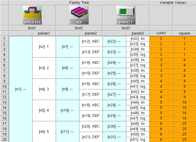
Figure 1. Horizontally orientated project with orange as the table background color as shown in the VAR1 and square columns. (Click image for full-size view.)
To change the title color:
- Choose Edit > Preferences, or press the F12 key.
- In the SWB Preferences dialog box, expand Table > Background.
- Change the color as required (see Figure 2).
- Click Apply.
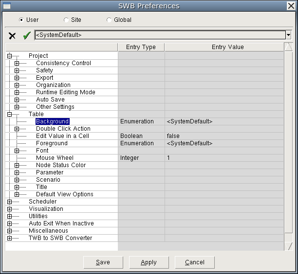
Figure 2. Changing the background color of the table. (Click image for full-size view.)
6.1.2 Changing the Project Orientation
You can change the project orientation: horizontal or vertical. For large projects with many splits, it is more convenient to have a horizontal orientation (see Figure 1).
Small projects with fewer splits look better with a vertical orientation (see Figure 3).
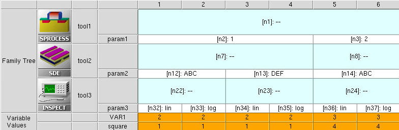
Figure 3. Vertically orientated project. (Click image for full-size view.)
To switch between the horizontal and vertical orientation for an open project, either:
- Choose View > Flow Orientation > Horizontal.
- Choose View > Flow Orientation > Vertical.
To choose the project orientation globally:
- Choose Edit > Preferences, or press the F12 key.
- In the SWB Preferences dialog box, expand Table > Default View Options.
- Change the value of Default Project Orientation (see Figure 4).
- Click Apply.
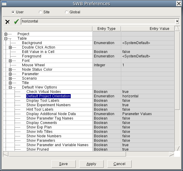
Figure 4. Changing the project orientation globally. (Click image for full-size view.)
6.2 Tree Navigation
The common strategy for data exchange between different tools in a Sentaurus Workbench project uses the concept of tree navigation, which is based on the fact that each node in a simulation tree has a unique number. When manipulating tool inputs, you can enter preprocessing commands (for example, #if and #include) and special @...@ constructions, which are evaluated and substituted during a project preprocess.
To show node numbers:
- Choose View > Tree Options > Node Numbers, or press Ctrl+2.
Press the F9 key to show both the node number and the parameter value in the same cell (see Figure 1).
6.2.1 Node Navigation
A complete Sentaurus Workbench project, showing the standard node navigation and parameter operations, is located in the directory Applications_Library/GettingStarted/swb/node_preprocess.
Load the project into Sentaurus Workbench and preprocess it (press Ctrl+P). Then, look at each particular node input (pp*.cmd) to see how the preprocessor interprets the commands.
The node number for each particular tool in a project can be accessed using the @node@ specification in a tool command file. For example, for the project in Figure 1, the following entries have been put into the first tool input (tool1) (click the command file tool1_fps.cmd):
| Node specification | Tool instance |
|---|---|
|
@node@ @node:2@ @node:+2@ @node:all@ @node:first@ @node:last@ @node|1@ @node|+1@ @node|+1:all@ #if @node@ != @node:first@ @node:-1@ #else none #endif @node:index@ @node:max@ @node|tool1@ @node|tool2@ @node|tool1:all@ |
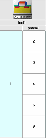 |
Table 1 illustrates how Sentaurus Workbench interprets these entries during the project preprocess. The Description column assumes horizontal project orientation. For vertical project orientation, the definitions of the words right and below in the description should be exchanged.
| Command entry | Result after preprocessing | Description |
|---|---|---|
| @node@ | 2 | Returns the current node number. |
| @node:2@ | 3 | Returns the number of the second node in the column. Here, a colon (:) is the operator used to navigate between different nodes within the same tool of the project. |
| @node:+2@ | 4 | Returns the node number that is two positions below the current node. For a vertically oriented project, it is two positions to the right of the current node (on the same tool level). |
| @node:all@ | 2 3 4 5 6 | Returns the list of node numbers in the current project level. |
| @node:first@ | 2 | Returns the number of the first node in the column. |
| @node:last@ | 6 | Returns the number of the last node in the column. |
| @node|1@ | 12 13 | Returns node numbers for the next subsequent
tool in the project that are in the same branch of the simulation
tree. Here, a vertical bar (|) is the operator to navigate between different tool nodes in the project. 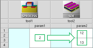 When navigating, only real nodes are counted. Virtual nodes (light-blue colored) are ignored. |
| @node|+1@ | 12 13 | The command is equivalent to @node|1@. |
| @node|+1:all@ | 12 13 14 15 16 17 18 19 20 21 12 13 14 15 16 17 18 19 20 21 | A list of all node numbers for the next subsequent tool in
the project. Numbers in the list are repeated according to a
number of splits on the next tool level (in this case, two
repetitions of the number set are produced). To produce the unique
node number list without repetitions, use the following commands: !( set nl [list @node|+1:all@] puts [lsort -unique $nl] )! which produces the required node list: 12 13 14 15 16 17 18 19 20 21 The !(...)! construction instructs Sentaurus Workbench that there are Tcl commands inside, which must be evaluated during node preprocessing. |
| #if @node@ != @node:first@ @node:-1@ #else none #endif |
none | Constructions such as @node:-1@, @node:+1@,
@node|-1@, and @node|+1@ must be used with care,
since they might refer to nonexistent node numbers. To avoid such
problems, it is recommended that you check using the #if command. In the example, for the first node in the column, the reference to the previous node does not exist. Therefore, the #if check returns the "none" value. |
| @node:index@ | 1 | Returns the index of the current node. |
| @node:max@ | 5 | Returns the index of the last node in the column, which is equivalent to the number of splits on the current tool level in the project tree. |
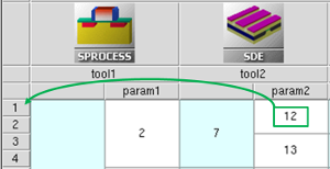
| @node|tool1@ | 2 | Returns the node number for the "tool1" tool name in the current branch of the simulation tree. Using the tool name for node navigation sometimes is more convenient, because you do not need to consider at which project tree level a node is located, but can directly access its number using a tool name. |
| @node|tool2@ | 12 13 | Returns the node numbers for the "tool2" tool name in the current branch of the simulation tree. This command is equivalent to @node|+1@. |
| @node|tool1:all@ | 2 3 4 5 6 | Returns the list of node numbers for the "tool1" tool name in the simulation tree. This command is equivalent to @node:all@. |
6.2.2 Reserved Keywords
There are other @...@ reserved keywords in Sentaurus Workbench, which can be useful for tree navigation and data analysis. The most frequently used keywords are collected in the second SDE tool input (tool2) of the project (click the command file tool2_dvs.cmd) shown in Figure 1.
| Keyword | Description |
|---|---|
| @previous@ | Returns the node number of the previous node in the tree branch.
Used to create node execution dependency
(see Section 6.2.3 Execution Dependencies). It cannot be used in the first tool input in the flow, for which a previous node does not exist. |
| @experiment@ | Returns the experiment number to which a node belongs.
 |
| @experiments@ | Returns all the experiments to which a node belongs as a list. |
| @tool_label@ | The label of a tool instance in the simulation flow.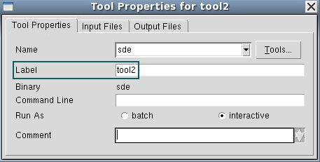 |
| @pwd@ | Returns an absolute path to the project depository. |
| @pwdout@ | Returns an absolute path to the project depository in hierarchical project organization. Takes into account the possibility of remote data location outside of the project directory. |
| @nodedir@ | Returns the path to the corresponding node folder for hierarchical project organization, relative to @pwdout@. |
| @tdrboundary@ | Returns the full name of the device structure boundary file, which is supposed to be loaded or saved in the current node. This command assumes that a boundary is created by either Sentaurus Process or Sentaurus Structure Editor, and it automatically substitutes the keyword with a proper file name. If specified in other tool inputs, this specification will generate a preprocessor error. |
| @tdr@ | Returns the grid file name, given in TDR data format, which appears to be a result of the preceding process simulation or meshing step. Sentaurus Workbench automatically assigns a name according to the provided tool sequence in the project. |
| @commands@ | Returns the tool preprocessed file name ready for execution. |
| Keyword | Description |
|---|---|
| @tdrdat@ | Returns a file name using the n<current_node_number>_des.tdr format, which is suitable for the Plot file specification in the File section of the Sentaurus Device command file. Therefore, it is usually used as a parameter of the Plot statement: Plot="@tdrdat@". |
| @plot@ | Returns a file name using the n<current_node_number>_des.plt format, which is suitable for the Current specification in the File section of the Sentaurus Device command file. It is used as a parameter of the Current statement, Current="@plot@", which refers to the results of the electrothermal device simulation, such as currents, voltages, time, temperature, and charges. |
| @log@ | Returns a file name using the n<current_node_number>_des.log format, which is suitable for the Output specification in the File section of the Sentaurus Device command file. Therefore, it is usually used as a parameter of the Output statement: Output="@log@". |
| @acplot@ | Returns a file name using the n<current_node_number>_ac_des.plt format. It is used as a parameter of the ACExtract statement in the File section of the Sentaurus Device command file, ACExtract="@acplot@", which refers to the results of small-signal AC analysis. |
| @parameter@ | Returns a file name using the n<current_node_number>_des.par format. It is used as a parameter of the Parameter statement in the File section of the Sentaurus Device command file, Parameter="@parameter@", which refers to the input parameter file, containing material properties and the kinetic model coefficients. |
6.2.3 Execution Dependencies
When running a project, the node execution order is defined by node dependencies. Sentaurus Workbench immediately submits all nodes that are ready for execution, assuming that all their prerequisite nodes have been executed already.
To have a node execution dependent on the successful completion of the previous node or nodes in the project tree, the special preprocess command #setdep can be used in the following form:
#setdep <list of nodes>
Having found such a command, the preprocessor ensures that a current node is not executed before all nodes in the list have the status "done".
| Command | Result |
|---|---|
| #setdep @node|-1@ | Sets the dependency on a previous node in the project tree branch. |
| #setdep @node|-1:all@ | Requests the node execution only when all nodes in the previous node column are finished. |
| @previous@ | Specifying @previous@ in the input automatically triggers a corresponding node dependency. |
To unset node dependency, use the #remdep command.
When a project remains in Editable mode (see Section 6.6 Runtime Editing Mode), selecting the Preprocess, then run option for nodes in the Run Project dialog box does not generate a node dependency. To activate node dependency, a project or node must be preprocessed explicitly by choosing Nodes > Preprocess or by pressing Ctrl+P.
In some cases, you might want to change this predefined project execution order. Sentaurus Workbench allows you to do this by setting a concurrency mode for experiments in the Run Project dialog box:
- Concurrency Mode: Unlimited is the default mode for project execution.
- Node running order is defined by the node dependencies.
- Nodes are executed on a tool-by-tool basis, when the earlier positioned tool nodes in the project are executed first.
- Concurrency Mode: Limited restricts the maximum number of running
experiments that can be executed simultaneously, by a given number.
- Nodes are executed on an experiment-by-experiment basis, and experiments with the smallest index are executed first.
- The number of simultaneously run experiments is given as input. This allows you to control the number of runs in case of limited computational resources or limited license availability.
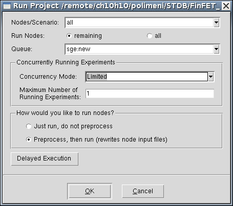
Figure 5. Run Project dialog box with Limited selected as the concurrency mode.
To make the limited concurrency mode the default:
- Choose Edit > Preferences.
- In the SWB Preferences dialog box, expand Scheduler > General Settings.
- Set Default Concurrency of Running Experiments to Limited.
- Click Apply.
If you have the Run Limits option switched on, it deactivates the concurrency mode and activates the run limits specified by users inside a dedicated runlimits.xml file. For details about the Run Limits option, refer to the Sentaurus™ Workbench User Guide.
6.2.4 The "/i" and "/o" Reference Options
Each @...@ reference in Sentaurus Workbench can have an option, specifying whether the reference addresses the input or output interface of a tool.
The possible flags (options) are:
- @<ABC>/i@ refers to the input file of type <ABC> for the current tool.
- @<ABC>/o@ refers to the output file of type <ABC> for the current tool.
If no option is specified, the Sentaurus Workbench preprocessor assumes the input file ("/i" option), which works seamlessly for most tools. The only exception is Sentaurus Structure Editor, for which you might want to either load input from the previous tool (for example, Sentaurus Process) or create input for the subsequent tool (for example, Sentaurus Mesh). This is where the "/i" and "/o" options are helpful.
For example, the following commands in the file tool2_dvs.cmd:
@tdrboundary/i@
@tdrboundary/o@
will be interpreted by the Sentaurus Workbench preprocessor for node 12 as:
n7_bnd.tdr
n12_bnd.tdr
6.3 Parameter and Variable References
This section discusses how to refer to project parameters and variables in Sentaurus Workbench.
6.3.1 Project Parameters
As mentioned in Section 4.1 Adding Parameters, a parameter splits the flow at the insertion point to produce variations in the current tool inputs. To access a parameter value, the syntax @<parameter_name>@ is used.
To demonstrate the possible ways to access parameter values, the following entries have been put into the Inspect tool input file (tool3) for the project (click the command file tool3_ins.cmd) shown in Figure 1:
@param1@
@param2@
@param3:+2@
@param2|-1:+2@
@param1:all@
@param1|-2:all@
The following examples show how the corresponding preprocessed entries for the first (upper) node in the column look after preprocessing.
| Command entry | Result after preprocessing |
|---|---|
| @param1@ | 1 |
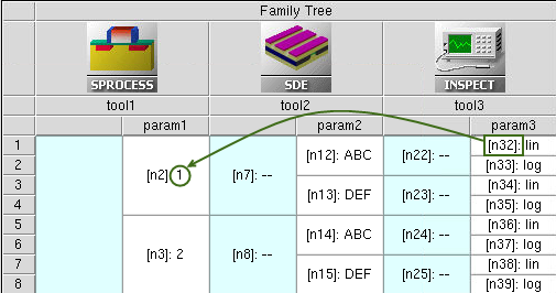
Figure 6. Reference by parameter name.
| Command entry | Result after preprocessing |
|---|---|
| @param2@ | ABC |
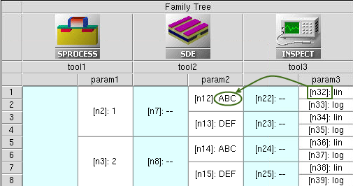
Figure 7. Reference by parameter name.
| Command entry | Result after preprocessing |
|---|---|
| @param3:+2@ | lin |
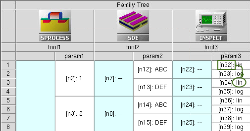
Figure 8. Combination of reference by parameter name and vertical node shift.
| Command entry | Result after preprocessing |
|---|---|
| @param2|-1:+2@ or @param2|:+2@ |
ABC |
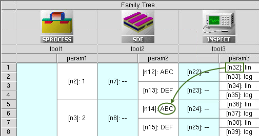
Figure 9. Combination of reference by parameter name, and vertical and horizontal node shifts.
| Command entry | Result after preprocessing |
|---|---|
| @param1:all@ | 1 1 1 1 2 2 2 2 3 3 3 3 4 4 4 4 5 5 5 5 |
| @param1|-2:all@ | 1 2 3 4 5 |
The @param1:all@ entry in the Inspect tool
instance produces the multiple-value param1 list according to the
number of subsequent splits in the Family Tree. To produce the original
list of values, the command should refer to the project tool location
where the parameter has been introduced (Sentaurus Process tool instance).
Alternatively, the list of values produced by @param1:all@
can be sorted using the Tcl lsort command:
!(
puts [lsort -unique [list @param1:all@]]
)!
6.3.2 Project Variables
Variables are special objects, introduced in Sentaurus Workbench, which are used to exchange extracted data values between project tools. Like a parameter, a variable holds a value and can be referenced in any form of the @...@ references. The main difference is that a variable does not create a split in the simulation flow and, therefore, does not change the simulation tree representation.
The #set command defines a preprocessed variable and initializes it:
#set <variable_name> <value>
A variable reference creates an execution dependency from the node where the reference is performed to the first ancestor where the variable has been set.
In this project, the variable "VAR1" is defined in the first Sentaurus Process tool instance as #set VAR1 @node@.
After project preprocessing, it appears as a single project column following the last tool in the project tool flow.
The last statement in the Inspect tool command file:
#set square @<@param1@*@param1@>@
illustrates how you can use a parameter in the equation expression and assign a resulting value to the variable, which then appears in the project view. The #set command here creates the variable and assigns its value. The resulting variable value appears on the rightmost side of the project view (see Figure 1, VAR1 column under Variable Values).
Another way to have a variable appear in the project is to print its name and value while a node is executed. This is the typical way in which extracted parameter values are sent to the project for further analysis. After a node has been executed successfully, Sentaurus Workbench parses the output file of the node for strings that match the following template:
DOE: <varname> <value>
Then, found values are written to the gvars.dat file and the project view is modified. If a specified variable already exists, the last printed value will overwrite an existing one.
Here are examples of how you can write a variable that will appear in a project view:
- In Sentaurus Structure Editor, use:
(define pi 3.141593)
(sde:display-std (string-append "DOE: PI " (number->string pi))) - In Inspect, use:
set pi 3.141593
ft_scalar PI $pi
6.3.3 Node Selection by Expression
For large DoE projects, selecting a restricted set of nodes by a given criterion might be a tedious task. This is where node selection by expression can help.
The project Applications_Library/GettingStarted/sdevice/MultiValleyMOS demonstrates how to use node selection by expressions.
To select nodes by an expression:
- Open the project.
- Choose Nodes > Select > By Expression.
- In the Select Nodes By Expression dialog box, enter the selection expression, as shown in Figure 10.
- Click OK.

Figure 10. Select Nodes By Expression dialog box.
Then, choose Nodes > Extend Selection To > Root. You should see the corresponding experiments are highlighted, as shown in Figure 11.
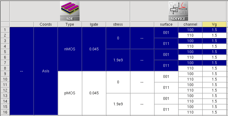
Figure 11. Selected experiments after being extended to roots. (Click image for full-size view.)
The general expression template consists of <scenario_name>:{<expression>}, where <scenario_name> represents the name of the experimental scenario ("all", for example), and <expression> consists of a single or multiple logical expressions.
The following examples demonstrate a variety of cases:
- Select all nodes in scenario "all" with the stress parameter value > 1:
all:{$stress > 1} - Select nodes in scenario "all" for the channel orientation != <100>:
all:{$channel != 100} - Inside a single expression, the Boolean logical AND operand (&&) is supported.
Select all nodes in scenario "all" with stress > 1 and the channel orientation <100>:
all:{$stress > 1 && $channel == 100} - Instead of <scenario_name>, the tool label can be used as follows:
sde:{$stress > 1} - Combine a scenario name with a tool label:
all|IdVg:{$channel == 100} - Superposition of expressions using binary operators is possible, for example:
– AND (intersection) operation:
all|IdVg:{$channel == 100} * all:{$Type == "nMOS"}– OR (union) operation:
all|IdVg:{$channel == 100} + all:{$Type == "nMOS"}– Difference operation:
all|IdVg:{$channel == 100} - all:{$Type == "nMOS"}
A similar method can be used to add selected experiments by expression to a new scenario.
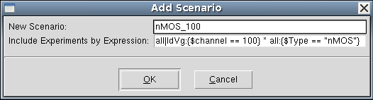
Figure 12. Add Scenario dialog box with experiments to be included by expression.
6.4 Input Customization
All tool inputs can be accessed from the user interface of Sentaurus Workbench by either choosing Tool > Edit Input, or right-clicking a tool icon and selecting Edit Input.
The corresponding tool inputs in the menu are tool oriented, and their definitions are specified in the global tooldb.tcl file, which is accessible by choosing Edit > Tool DB > Global.
For example, as shown in Figure 13, right-click the Sentaurus Device tool icon, select Edit Input, and then select one of the available options.
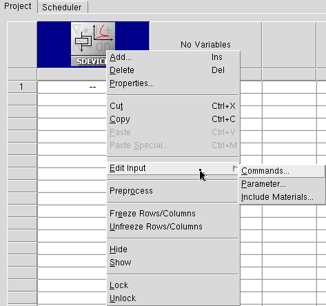
Figure 13. Options of Edit Input for Sentaurus Device.
Each Sentaurus Device tool instance uses a unique command file. On the other hand, by default, all Sentaurus Device tool instances in a project share the same material parameter file sdevice.par.
If multiple Sentaurus Device instances are used in a project, Sentaurus Workbench also allows individual Sentaurus Device parameter files. To activate an individual parameter file, you must indicate it in the corresponding tool properties, as shown in Figure 14.
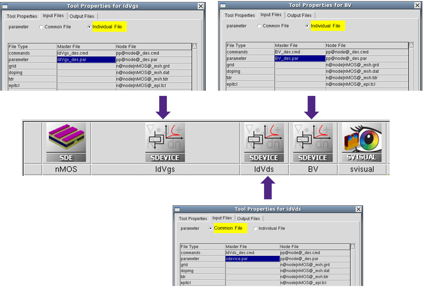
Figure 14. Diagram showing customization of individual parameter files for multiple Sentaurus Device tools in a project. (Click image for full-size view.)
To create a project from the beginning and to include different material parameters in your parameter file that does not yet exist:
- Choose Tool > Edit Input > Parameter.
- In the Create Parameter File dialog box (see Figure 15), select
the Choose Materials option to see the list of supported materials.
Materials shown in green exist in the Sentaurus Device material database (MaterialDB), supplied with the release. - Select the materials required.
- Click OK.
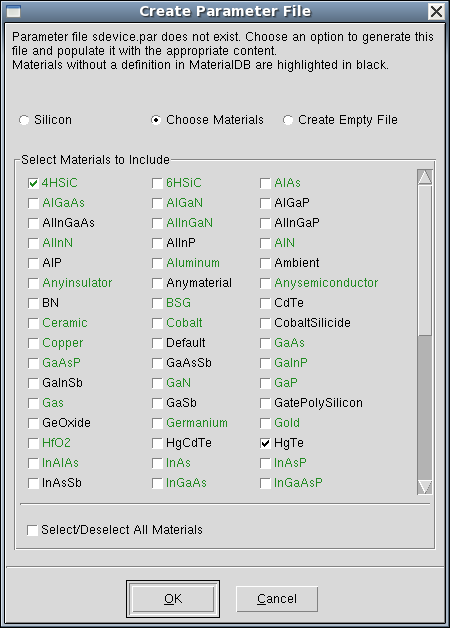
Figure 15. Create Parameter File dialog box showing Choose Materials option selected.
The corresponding material parameter files will be copied to the current project directory and referred to in the actual parameter file, as shown in the following example (a warning message is displayed for a non-existent material):
#define ParFileDir .

Material="4HSiC" {
  #includeext "ParFileDir/4HSiC.par"
}
Material="HgTe" {
  # WARNING: no parameter file found for material HgTe in the material database
}
As already mentioned, the input listed in the Edit Input submenu of each tool is defined in the global tooldb.tcl.
If you need to modify the submenu (input list), you can customize it by introducing the necessary corrections in a local project gtooldb.tcl file. The following example shows how you can do this.
Look at the project, which consists of one Sentaurus Device tool instance and one parameter (see Figure 16).
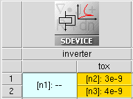
Figure 16. Example showing how to customize the input file list for the Sentaurus Device tool instance.
The corresponding Sentaurus Workbench project can be copied from the directory Applications_Library/GettingStarted/swb/HSpice_bsim4.
In this project, the CMOS inverter behavior is simulated on a circuit level using the Synopsys HSPICE® BSIM4 circuit model. The BSIM4 model parameters for the NMOS and PMOS transistors are loaded from the external file circuit.scf, where the parameter tox is referred.
To ensure that this file can be parameterized, the local project gtooldb.tcl file has been modified.
The first three commands add a new object (circuit) to the file type list, define its standard file extension (scf), and add the new object to the Sentaurus Device input file list:
set WB_tool(file_types) [list circuit]
set WB_tool(circuit,ext) scf
set WB_tool(sdevice,input) [list commands parameter config grid doping edit\
 tdr circuit]
The next four commands specify the full circuit file name, which must be opened when selecting the corresponding item from the Edit Input submenu, select the label in the tool Edit Input submenu, activate the possibility to parameterize this file, and indicate that a default text editor must be used to edit this input:
set WB_tool(sdevice,input,circuit,file)  circuit.scf
set WB_tool(sdevice,input,circuit,label)  "Circuit..."
set WB_tool(sdevice,input,circuit,parametrized)  1
set WB_tool(sdevice,input,circuit,editor)  text
This makes it possible for:
- The circuit file to appear in the list of Sentaurus Device inputs.
- The circuit.scf file to be parameterized.
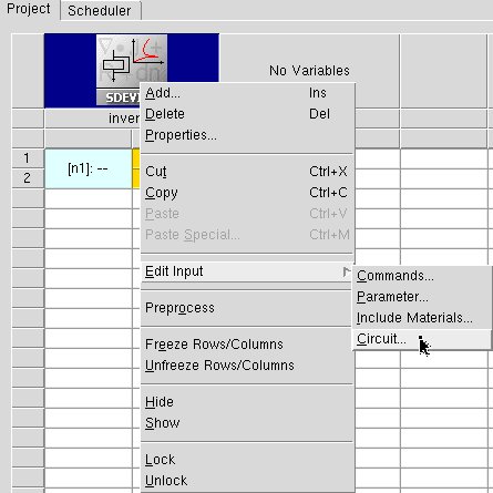
Figure 17. Modified input file list for Sentaurus Device, introducing the possibility to edit the circuit file description (compare with Figure 13).
Preprocess the project to see how the @tox@ statement is replaced by its actual values.
At the end of the gtooldb.tcl file of the project, you can see an additional command, instructing Sentaurus Workbench that the prologue commands must be executed before the execution of a Sentaurus Device node:
set WB_tool(sdevice,prologue) { catch {os_mkdir_rel n@node@ $wdir}; os_cp\
 $wdir/pp@node@_des.scf $wdir/n@node@/pp@node@_des.scf  }
The purpose of these commands is to create a subdirectory in the project directory and to copy a preprocessed circuit file there. This is performed to overcome a Sentaurus Device limitation, which is always to read the first-found circuit file in the directory specified using the SPICEPath keyword.
Correspondingly, Sentaurus Device is instructed to read the circuit file from a specific "./n@node@" path to avoid any misuse of the circuit file:
File {
  ...
  SPICEPath= "./n@node@"
}
6.5 Visualize Selected Nodes Together
One of the most common tasks in Sentaurus Workbench is to compare simulation characteristics of different experiments to each other.
You can easily use this functionality when coding your visualization scripts. The project GettingStarted/swb/SimpleMOS demonstrates this capability for Sentaurus Visual. However, the approach applies to any visualization tool.
Start Sentaurus Workbench, copy and open the project, and run all the nodes. Then, select several Sentaurus Visual nodes that correspond to the same Vd bias condition. Alternatively, you can select these nodes by an expression as follows:
- Right-click a node.
- Choose Select > By Expression.
- In the Select Nodes By Expression dialog box, enter all|last:{$Vd==1.0}.
- Click OK.
For more details, see Section 6.3.3 Node Selection by Expression.
After you select the nodes, click the Run Selected Visualizer Nodes Together toolbar button to generate all of the corresponding curves in Sentaurus Visual as shown in Figure 18.
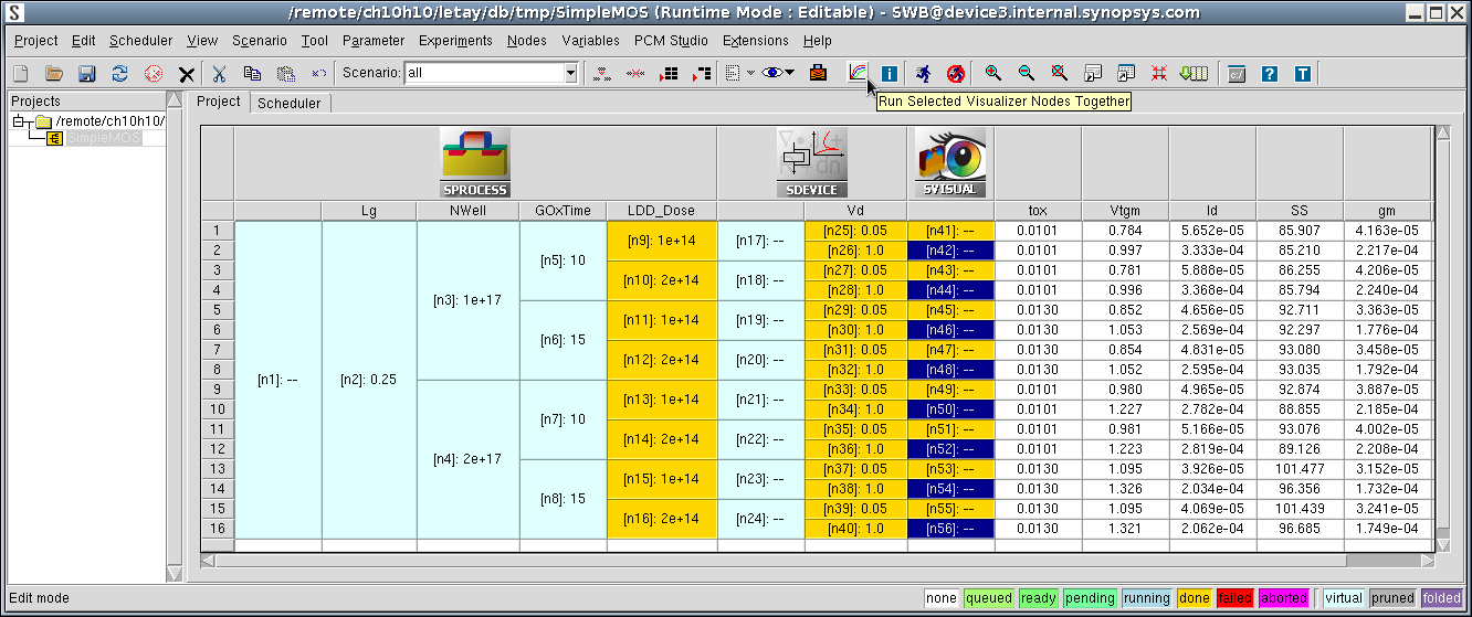
Figure 18. SimpleMOS project showing the toolbar button to launch all visualization scripts together. (Click image for full-size view.)
Sentaurus Visual assembles all of the corresponding Id–Vgs curves in one plot (see Figure 19). The legend contains only those Sentaurus Workbench parameters required to uniquely identify each selected curve.
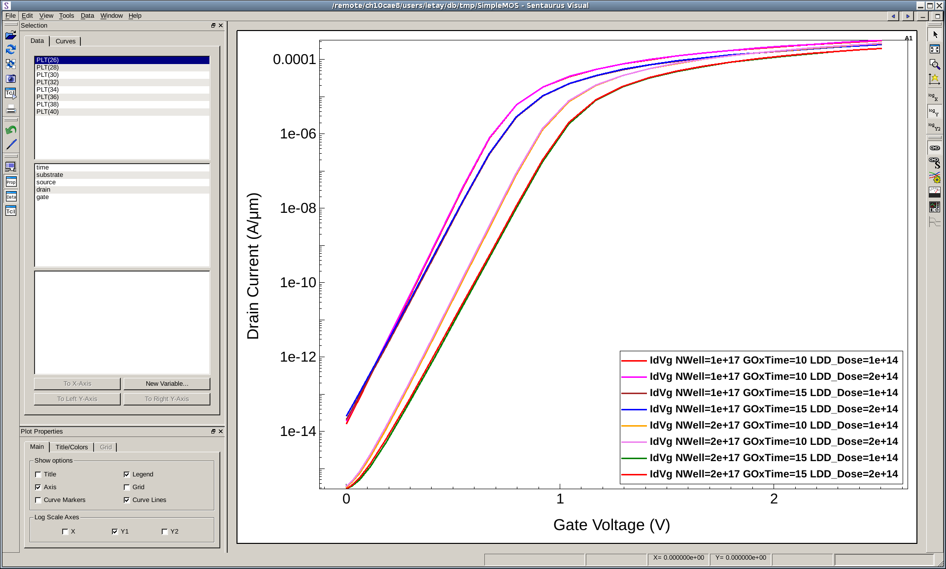
Figure 19. Assembled Sentaurus Visual curves. (Click image for full-size view.)
Technically, Sentaurus Workbench performs the following steps when you click the Run Selected Visualizer Nodes Together button:
- It checks whether any visualization nodes need to be preprocessed.
- It runs preprocessed command files of all the selected nodes sequentially in one Sentaurus Visual instance.
In this way, the following variables are set:
- nodelist: List of node numbers of all selected nodes
- legend: Legend text of the current curve
- commonParameters: String containing all keyword–value pairs common to all selected nodes
- cv_index: Index of the current curve, starting from 1
- runVisualizerNodesTogether: Set to 1 to check the run mode if a script was called using the toolbar button
As the preprocessed command files are executed sequentially in the same Sentaurus Visual session, consider the following points:
- Unique names: Any variable, dataset, and curve name that is created in the script must be unique. This is easily achieved by including a unique node number @node@, for example, create_curve -name IdVg(@node@)...
- Execute code only once: Certain operations such as creating a plot
frame must be executed only once. This can be accomplished by using:
if {[llength [list_plots Plot_1D]]==0} { create_plot -1d -name Plot_1D ... } - Detect visualization mode: Executing multiple nodes can be time consuming.
For a fast response, you might separate expensive postprocessing from pure curve visualization
tasks. Whether the script is called in batch mode or in visualization mode, can be determined by:
# set curve properties only if script is called through run visualizer button if {[info exists runVisualizerNodesTogether]} { set_curve_prop IdVg($n) -label "IdVg(n$n) $legend" \ -color $color -line_style solid -line_width 3 ... } - Detect node status: Visualization can also be performed during simulation.
To check the current node status, specify:
# determine sdevice node status
set status @[gproject::GetNodeStatus @node|sdevice@]@
...
# Extract curve parameters only when sdevice node has status done if { $status == "done" } { load_library extract ... } - script_break (in Inspect): Do not use this command. Otherwise, evaluation stops at the first break in the first curve.
Click to view the commented Sentaurus Visual command file IdVg_vis.tcl.
6.6 Runtime Editing Mode
A project can be configured to have different runtime editing modes:
- In the Editable mode:
- Sentaurus Workbench deactivates all safeguards.
- Users have maximum flexibility when running projects.
- Users are wholly responsible for maintaining project consistency.
- In the Locked mode:
- Sentaurus Workbench handles projects as in earlier releases (before K-2015.06).
- Sentaurus Workbench activates safeguards to keep overall project consistency.
The Editable mode is the default for a newly created project. For projects created with earlier Sentaurus Workbench releases, the mode is taken according to the preferences.
To change the runtime editing mode:
- Choose Edit > Preferences, or press the F12 key.
- In the SWB Preferences dialog box, expand Project > Runtime Editing Mode > Default Mode.
- Change the mode.
- Click Apply.
For an already loaded project, to change the runtime editing mode, you can either:
- Choose Project > Runtime Editing Mode > Locked.
- Choose Project > Runtime Editing Mode > Editable.
Every time a project is loaded, its mode is taken according to the setup from the previous session.
The runtime editing mode is shown in the title bar of the main window of Sentaurus Workbench, where the full project name is shown.
Table 5 summarizes the differences between the two modes in terms of user ability to control the execution of project nodes.
| Running project criteria | Editable mode | Locked mode |
|---|---|---|
| Running project is locked for changes. | No | Yes |
| Automatic checks of project consistency, file timestamps, and execution dependencies. | No | Yes |
| Modifications to tool input files on a node level are allowed. | Yes | No |
| Nodes are forced to be preprocessed when they are run. | Yes | No |
| Modifications to tool input files and tool database files are allowed. | Yes | No |
| Parameterization table accepts changes: 1. Add or remove tools, parameters, and variables. 2. Add or remove experiments or parameter values. 3. Change a parameter value on a node. |
Yes | No |
| Modifications can remove or affect already running nodes. | No | No |
| Preprocessing the entire project or selected nodes is allowed. | Yes | No |
| Adding additional nodes to run, or terminating a project or nodes, is allowed. | Yes | Yes |
When you run a project in Editable mode, the Run Project dialog box is displayed (see Figure 20).
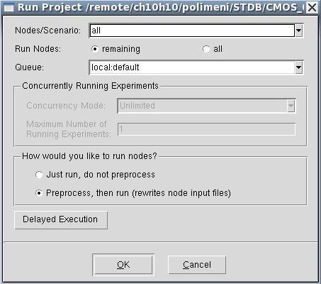
Figure 20. Run Project dialog box when project is in Editable mode.
By default, the Preprocess, then run option is selected, which instructs Sentaurus Workbench to preprocess the selected nodes before the execution. This ensures clean nodes are preprocessed before being run. If all nodes are already preprocessed, select the Just run, do not preprocess option to save time when preprocessing.
To preprocess or not preprocess nodes before they are run can be changed in the preferences as follows:
- Choose Edit > Preferences, or press the F12 key.
- In the SWB Preferences dialog box, expand Project > Runtime Editing Mode > Settings for Editable Mode > How to run nodes by default.
- Change the value.
- Click Apply.
main menu | module menu | << previous section | next section >>
Copyright © 2017 Synopsys, Inc. All rights reserved.